


 English
 中文简体
中文简体
+86-0575-8215 2808
/8200 8688/8239 2526

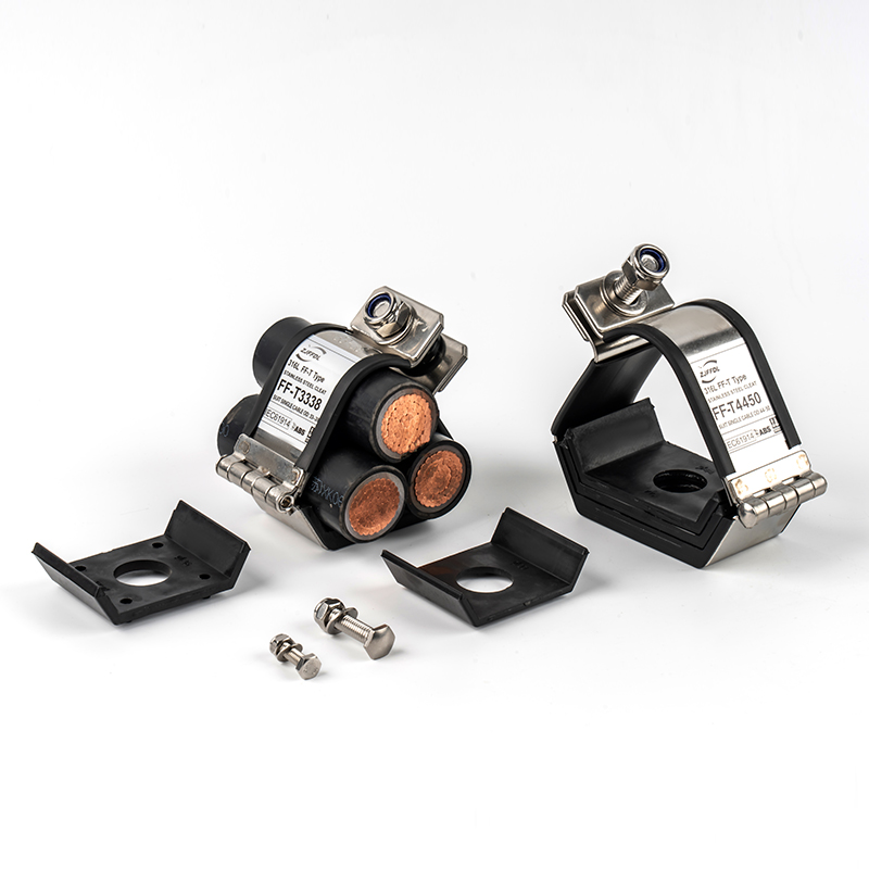
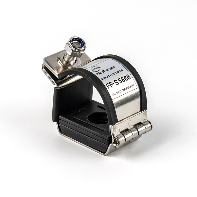
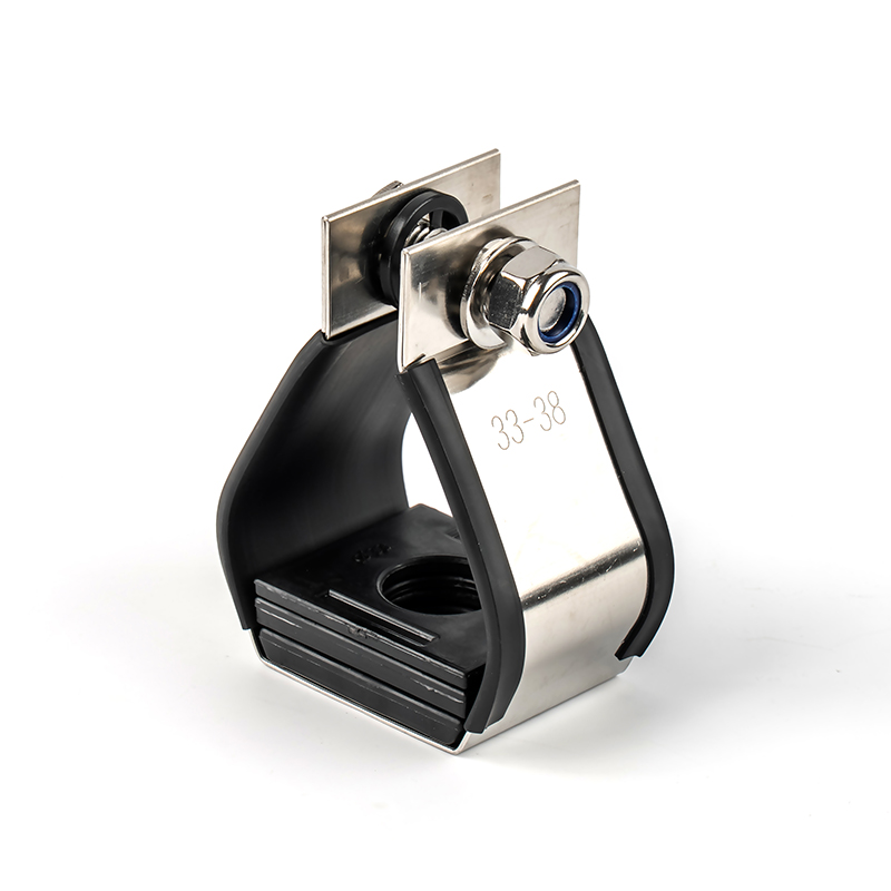
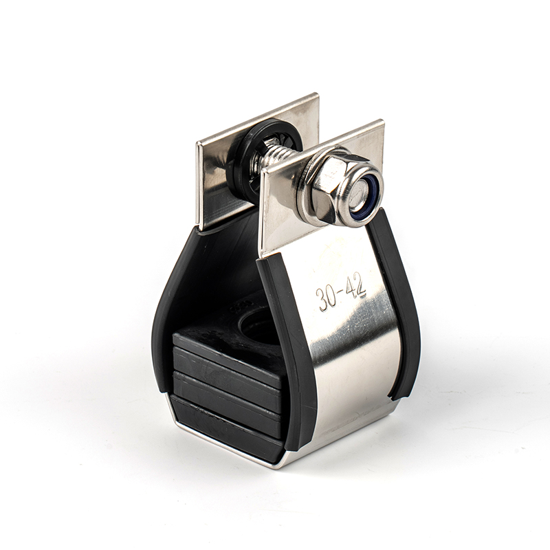
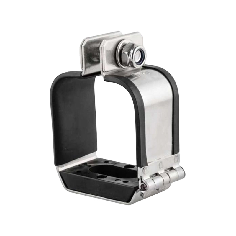
The single cable Cleats made of 316 stainless stee...
View more
Manufactured from high-grade 316 stainless steel, ...
View more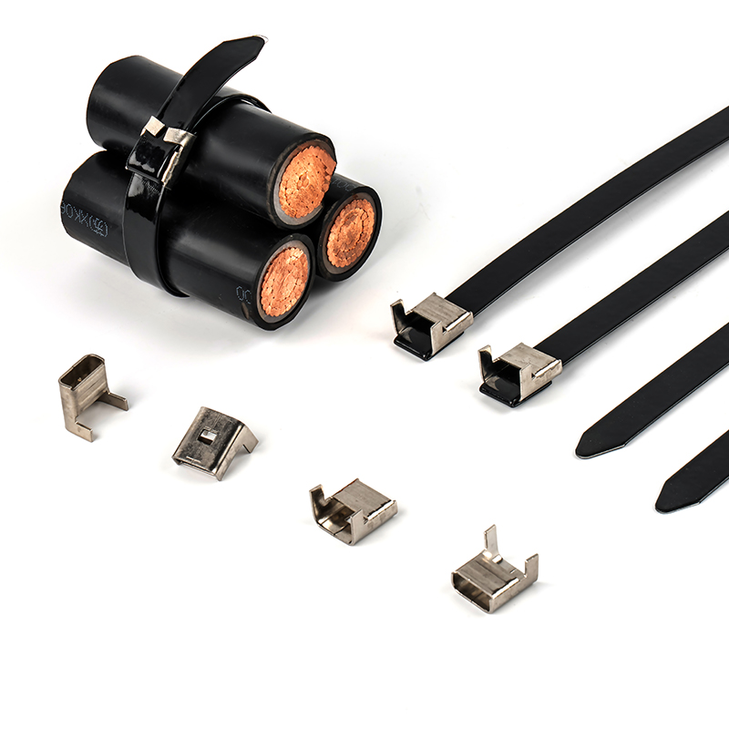
Brand Name: FengfanApproved Certificate: DNV &...
View moreContent
Cable cleats are the mechanical restraint that keeps power cables locked in position when a short circuit strikes. During a fault, the magnetic field around a cable can generate forces strong enough to fling unrestrained conductors apart with enough energy to crack cable trays, snap conduit, and injure anyone standing nearby. A properly rated cable cleat absorbs that force, holds the cable geometry fixed, and stops a single fault from becoming a cascading failure. That single function — controlled containment under fault current — is why cable cleats are treated as safety-critical hardware rather than a simple cable tray accessory.
When a short circuit occurs, current can spike from a normal operating level to tens of thousands of amps within a few cycles. Two current-carrying conductors running side by side create opposing or attracting magnetic fields, and the resulting electrodynamic force grows with the square of the fault current. A 40 kA fault on cables spaced 150 mm apart can generate a peak force exceeding 3.5 kN per meter of run — enough to bend unsecured cable trays or shear plastic ties in a fraction of a second.
Cable cleats are engineered and tested specifically against this scenario. Under standards such as IEC 61914, a cleat is rated for a defined peak fault current and a defined mounting spacing, meaning the manufacturer has already verified the hardware survives the mechanical shock rather than just holding static weight.
The correct cleat layout depends on how the cables are grouped on the tray. Choosing the wrong configuration undermines the fault rating even if the cleat material is correct.
FENGFAN produces all three layouts in 316 stainless steel, including the ER Series and standard trefoil models, the ES, VRT, and VRS single-cleat series for ladder-mounted runs, and the FFQ quad series for clustered installations.
Each series below is built from 316-grade stainless steel and tested for short-circuit withstand, corrosion resistance in saline air, and long-term UV exposure — the three conditions that most commonly cause premature cleat failure on offshore and marine projects.
Cleat selection is a three-step process, and skipping any one step results in either an unusable fit or a hardware set that cannot survive its intended fault level.
As a working example, a 400 mm² XLPE single-core cable typically has an OD around 42 to 45 mm. Paired with a correctly sized single cleat at 300 mm spacing, this combination is commonly specified for medium-voltage feeder runs rated up to 31.5 kA.
Most heavy-duty cleats combine a stainless steel band or frame with a polymer liner or coating. The steel component carries the mechanical load; the polymer component protects the cable jacket from abrasion and, in coated versions, adds a layer of corrosion and dielectric protection.
This is also where Weather Resistant Acetal components play a role — acetal-bodied fittings hold dimensional stability under UV and temperature cycling better than standard nylon, which matters for any cleat hardware left exposed on an open deck or rooftop plant room.
A frequent design mistake is substituting a heavy-duty cable tie for a cleat on a fault-rated circuit. The two products solve different problems and are rarely interchangeable on the same power feeder.
Cable ties still have their place downstream of the cleat, for tidying slack, dressing cable ends, or bundling instrumentation cabling that carries no meaningful fault current. Nylon Coated Stainless Steel Ties and Ball Lock semi-coated ties are common choices where a tie needs both mechanical strength and a non-abrasive coated surface against the cable jacket. Stainless Steel Strapping fills the gap for continuous coil-fed runs where individual ties would be too slow to install. None of these, however, replace a certified cable cleat on a circuit where short-circuit withstand is a design requirement.
Cable cleats are specified wherever a fault-related cable failure would be expensive, dangerous, or both.
In each of these settings, Cable Markers are typically installed alongside the cleat run so maintenance crews can identify circuits without disturbing the fixed cable geometry — a small detail that saves significant downtime during fault investigation.
A cable cleat that is correctly rated, correctly spaced, and properly torqued does its job silently for decades. The moment it is asked to do that job matters most is during a fault — which is exactly when there is no opportunity to fix an installation mistake after the fact.
The single cable Cleats made of 316 stainless steel is used for cable management. It is corrosion-resistant, high-temperature resistant and meets international standards. It is suitable for various ha...
See Detail
Manufactured from high-grade 316 stainless steel, this cable management system is specifically designed for secure cable retention in power generation, petrochemical, marine, offshore platforms, and c...
See Detail
Brand Name: FengfanApproved Certificate: DNV & ABS.Product Description: Cable Fixing Band and ClipsThe Lower Cost Alternative to Cable Cleats Product Benefits- Low profile finish- 316 grade stain...
See DetailMobile: +86-136 7685 3958
Email: lihai.fan@zjffdl.com
Mobile: +86-188 57530390
Email: alan.huang@zjffdl.com
No. 1116 Yasha Ave, Cao’e Street, Shangyu District, Shaoxing City, Zhejiang, China, 312300


+86-0575-8215 2808
/8200 8688/8239 2526

+86-0575-8215 2066
Copyright ©Zhejiang Fengfan Cable Fittings Co.,Ltd.
