


 English
 中文简体
中文简体+86-0575-8215 2808
/8200 8688/8239 2526

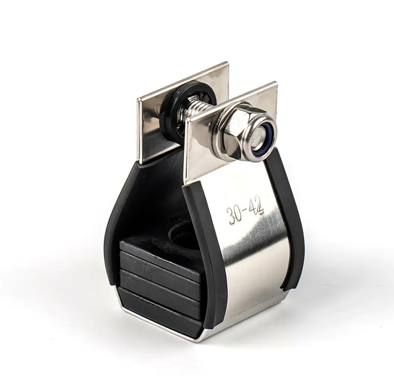
The single cable Cleats made of 316 stainless stee...
View more
Manufactured from high-grade 316 stainless steel, ...
View more
Brand Name: FengfanApproved Certificate: DNV &...
View moreContent
Cable cleats are not optional accessories—they are critical safety devices designed to secure electrical cables and prevent catastrophic damage during short-circuit events. A short-circuit fault generates electromagnetic forces proportional to the square of the peak current, capable of whipping energized cables through equipment racks and endangering personnel within milliseconds. Circuit breakers typically require 0.06 to 0.1 seconds to trip, but peak destructive force occurs at just 0.005 seconds on a 50Hz system. Cable cleats perform their restraining function instantly, before protection devices can react, making them the primary line of defense against electromechanical forces.
According to IEC 61914, cable cleats are defined as "devices designed to provide securing of cables when installed at intervals along the length of the cables." Unlike cable ties or standard clamps, cleats are specifically engineered and tested to withstand short-circuit forces, with ratings based on peak prospective short-circuit current (kA) and installation spacing.
During a three-phase short circuit, adjacent conductors produce intense electromagnetic fields. The repulsive force between conductors is proportional to the square of the peak short-circuit current, creating instantaneous stress that standard cable management products cannot contain. In a data center, unsecured cables can destroy server racks worth months of replacement time; in industrial settings, the same scenario risks fire, injury, and prolonged downtime.
Understanding the timeline of a fault event reveals why passive restraint is irreplaceable:
This timing gap means that no active protection device can prevent the initial mechanical destruction—only properly specified cable cleats can.
Selecting the correct cleat type depends on cable configuration, voltage class, and environmental conditions. Using an incompatible cleat type can result in inadequate restraint during fault conditions.
| Cleat Type | Cable Configuration | Typical Application |
|---|---|---|
| Single Cable Cleats | Individual single-core or multicore cables | Substations, control panels, general LV to HV runs |
| Trefoil Cable Cleats | Three single-core cables in triangular formation | High-current three-phase circuits, space-constrained installations |
| Quad Cable Cleats | Four single-core cables in quad formation | Parallel circuits, high-power distribution networks |
| Fire-Resistant Cleats | Various configurations with LSZH materials | Tunnels, rail infrastructure, oil and gas facilities |
| Stackable/Boltless Cleats | Multiple cables in vertical arrangements | Data centers, cable risers, confined spaces |
Material choice directly impacts performance lifespan and safety margins:
IEC 61914:2021 is the globally accepted standard for cable cleat design and testing, replacing the ambiguity found in regional electrical codes. While NEC Article 392.20(C) and CSA Article 12-2202 require cables to be secured against fault-current magnetic forces, neither specifies how to test or verify that restraining devices will survive a short-circuit event. IEC 61914 fills this critical gap.
The standard requires comprehensive testing across multiple performance dimensions:
A critical distinction: IEC 61914 requires short-circuit testing duration of just 0.1 second (five complete cycles), which is sufficient to expose cleat weakness because the peak destructive force occurs within the first few milliseconds. This differs from cable thermal withstand tests, which may specify 63kA for 1 second or 40kA for 3 seconds—those ratings address conductor heating, not mechanical restraint.
Proper specification requires matching the cleat's declared performance to the installation's actual fault conditions. Under-specification creates catastrophic safety risks, while over-specification wastes budget without added benefit.
Engineers must calculate and verify the following:
Consider two manufacturers claiming 140kA peak withstand:
For a system with 60kA fault level using 30mm cable at 1200mm spacing, Manufacturer B's product would fail despite the identical headline rating. This demonstrates why procurement teams must review complete test reports—not just headline figures—and why engineers must protect specifications throughout the project lifecycle.
Even correctly specified cleats can fail if installed improperly. Installation quality directly determines whether the system performs as tested.
Cable systems fall into two categories, each with distinct cleat requirements:
Cable cleats are essential wherever high-power cables run near personnel or critical equipment. The voltage level is irrelevant—some of the highest fault levels occur in low-voltage installations due to lower system impedance.
| Application Sector | Primary Risk Mitigated | Typical Cleat Requirements |
|---|---|---|
| Data Centers | Server rack destruction, service interruption | Stainless steel, boltless designs, stackable for density |
| Utility Tunnels & Vaults | Confined space hazards, multi-system cascade failure | Corrosion-resistant, high kA ratings, fire-resistant options |
| Refineries & Power Plants | Fire ignition, explosive atmosphere damage | Stainless steel 316, extreme temperature ratings |
| Rail & Transport Infrastructure | Service disruption, passenger safety in tunnels | Fire-resistant, low-smoke zero-halogen (LSZH) materials |
| Renewable Energy | Wind turbine downtime, solar farm cable damage | UV-resistant, weather-resistant, high mechanical strength |
In addition to safety compliance with NEC 392.20(C) and IEC 61914, proper cleat installation helps meet seismic requirements and insurance policy conditions, reducing liability and preventing costly rework.
Cable cleats represent a small fraction of total project cost but provide irreplaceable protection against short-circuit electromechanical forces. The selection process must integrate cable diameter, fault current calculations, spacing requirements, material compatibility, and environmental exposure into a cohesive specification. Procurement teams should treat cleats as engineered safety components—not commodity items—and verify that products carry independent test reports to IEC 61914:2021, including before-and-after short-circuit test documentation. By specifying and installing cable cleats correctly from day one, electrical contractors and facility owners ensure regulatory compliance, protect critical infrastructure, and create safer working environments for personnel.
The single cable Cleats made of 316 stainless steel is used for cable management. It is corrosion-resistant, high-temperature resistant and meets international standards. It is suitable for various ha...
See Detail
Manufactured from high-grade 316 stainless steel, this cable management system is specifically designed for secure cable retention in power generation, petrochemical, marine, offshore platforms, and c...
See Detail
Brand Name: FengfanApproved Certificate: DNV & ABS.Product Description: Cable Fixing Band and ClipsThe Lower Cost Alternative to Cable Cleats Product Benefits- Low profile finish- 316 grade stain...
See DetailMobile: +86-136 7685 3958
Email: lihai.fan@zjffdl.com
Mobile: +86-188 57530390
Email: alan.huang@zjffdl.com
No. 1116 Yasha Ave, Cao’e Street, Shangyu District, Shaoxing City, Zhejiang, China, 312300


+86-0575-8215 2808
/8200 8688/8239 2526

+86-0575-8215 2066
Copyright ©Zhejiang Fengfan Cable Fittings Co.,Ltd.
